

Stationary Spherical Near-Field Solutions - NSI-MI
Various models are available, each optimized for a particular class of antennas and application. The selection of the ideal Stationary SNF system will depend on the size of your DUT, the operating frequency, and desired mounting orientation. Learn more about our Stationary Spherical Near-Field Solutions below.
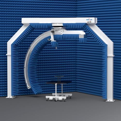
The spherical near-field vertical arch measurement system, SNF-ARCV-2.4, is an ideal solution for measuring radiation characteristics of non-moving antennas that do not require full spherical coverage and cannot be tested using the planar near-field technique. Three axes of motion revolve around the stationary AUT and an arch frame continuously rotates in the phi axis at speeds up to five revolutions per minute. The theta axis carriage carries the measurement probe through 115° of travel along the arch frame, with a linear slide providing precise real time radial adjustment. Proprietary error correction technique is used to further enhance its global accuracy. The versatile system is suitable for advanced phased array and general purpose antenna testing. Download data sheet here.
Features
- High positioning accuracy and repeatability
- Radiation pattern testing of stationary antennas
- Accurate probe motion from 0-115° in theta
- Rotary positioner provides 360° phi rotation of arch
- Automatic electronic alignment capability
- 3D dynamic on-the-fly probe position correction
- Multi-beam, multi-frequency control of RF subsystem
Features
- Radiation pattern testing of fixed mounted antennas
- Scanning arch provides accurate probe motion over ±95 degrees in theta
- Rotator provides 360° phi rotation of arch
- Automatic electronic alignment capability
- Dynamic on-the-fly probe position correction subsystem
- Multi-beam, Multi-frequency control of RF subsystem
- Optimized with NSI-MI data acquisition and processing software
High-Frequency Spherical Scanning with Integrated RF Stability
The SNF-FIX-1.0 is ideal for measuring stationary mmWave on-chip antennas and applications from 10 GHz up to 300.0 GHz. It uses a multi-axis high accuracy stepper motor-driven system to position the probe on a spherical surface while the antenna-under-test (AUT) remains stationary. The system is large enough to incorporate RF converter modules from OML and VDI as part of the probe carriage assembly and maintain a probe tip radius of roughly 500 mm (20 in.). Individual mmWave modules can be swapped to cover the relevant frequency bands, leaving the rack and cabling portion of the RF sub-system intact, thus making for a very modular and upgradable test system. All positioners contain integrated RF rotary joints, maximizing cable phase stability under test as well as slip-ring assemblies in the phi and theta axis positioners. Download data sheet here.
Features
- X-band to mmWave measurements
- 3D far-field, near-field, and holographic patterns
- Measurement sphere up to 1.0 m (.3 ft) diameter
- Stationary AUT
- Automatic alignment capability
- High accuracy and position repeatability
- Far-field measurement options available
- Low cost and portable


